Our Technologies
Four layers.
One platform.
Every Prime system is built on the same integrated technology stack. Cell chemistry, battery management, site control, and cloud analytics are engineered to work together; consistent, predictable behaviour from commissioning through end of life.
01 / 04 Energy Management System
Full visibility of every plant,
from anywhere.
The Prime EMS gives operators a single interface for every plant in their portfolio; live performance data, state of health, alarm history, and remote control in one place. Whether managing one plant or many across multiple countries, the data is always current.
Hosted in a European data center and accessible from any browser — no local software to install, no client to maintain. Any plant in the portfolio is a sign-in away.
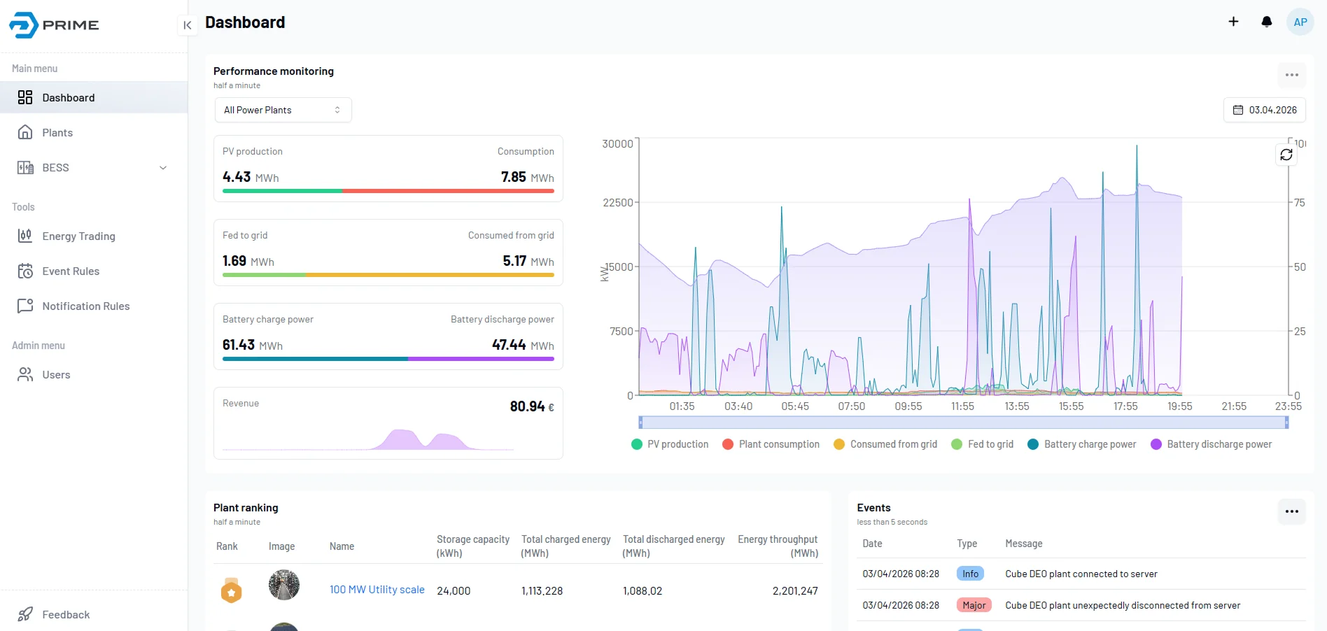
Live system health
Real-time data on state of charge, state of health, temperature, and power flow across every rack in every plant. Fault events are logged with full context for rapid diagnosis; no plant visit required.
Charge and dispatch control
Schedule charge and discharge cycles around tariff windows, renewable production, and demand patterns. The system continuously adapts dispatch to maximize the value delivered from stored energy.
Performance reporting
Historical data and exportable performance reports for every asset. Designed to support operational reviews, warranty claims, and degradation tracking across the full system lifetime.
Operations
Integration
02 / 04 On-site Gateway
Site control that works
independent of the cloud.
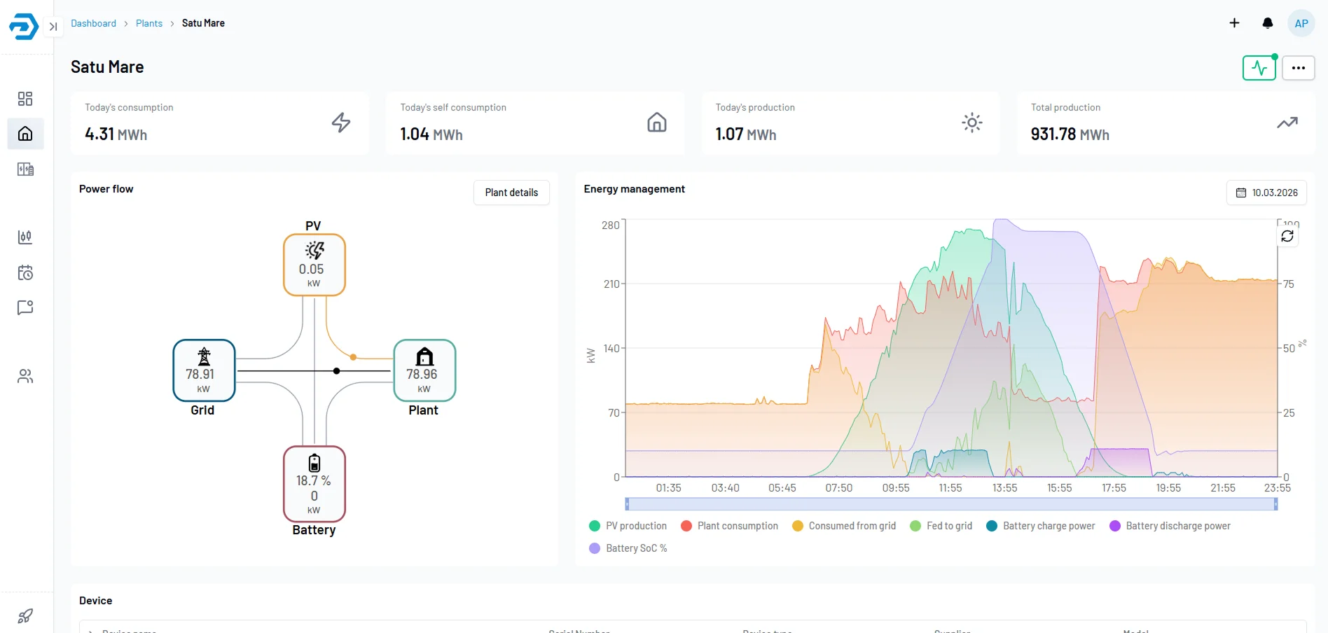
The on-site gateway handles all local control logic: peak shaving, scheduling, power quality, and protection coordination. It operates autonomously; if the internet connection drops, the plant continues running exactly as configured.
For installation and commissioning teams, the gateway provides a local web interface accessible directly over Ethernet; no cloud login or external network required. All system parameters, live data, and diagnostic tools are available on-site from day one.
Site control functions
Interoperability
03 / 04 Power Conversion
Power conversion matched
to the application.
Three inverter tiers cover the full range from commercial and industrial installations through utility-scale BESS. Each is validated and integrated into Prime skids against our cell chemistry, BMS, and EMS; the correct tier is selected at design stage based on DC bus voltage, power requirements, and grid connection type.
Round-trip efficiency is measured across the full load range. The figure is sustained from 20% to 100% load; covering real-world BESS dispatch including partial-load frequency regulation and overnight charge cycles. All tiers are IEC certified and compliant with European grid codes.
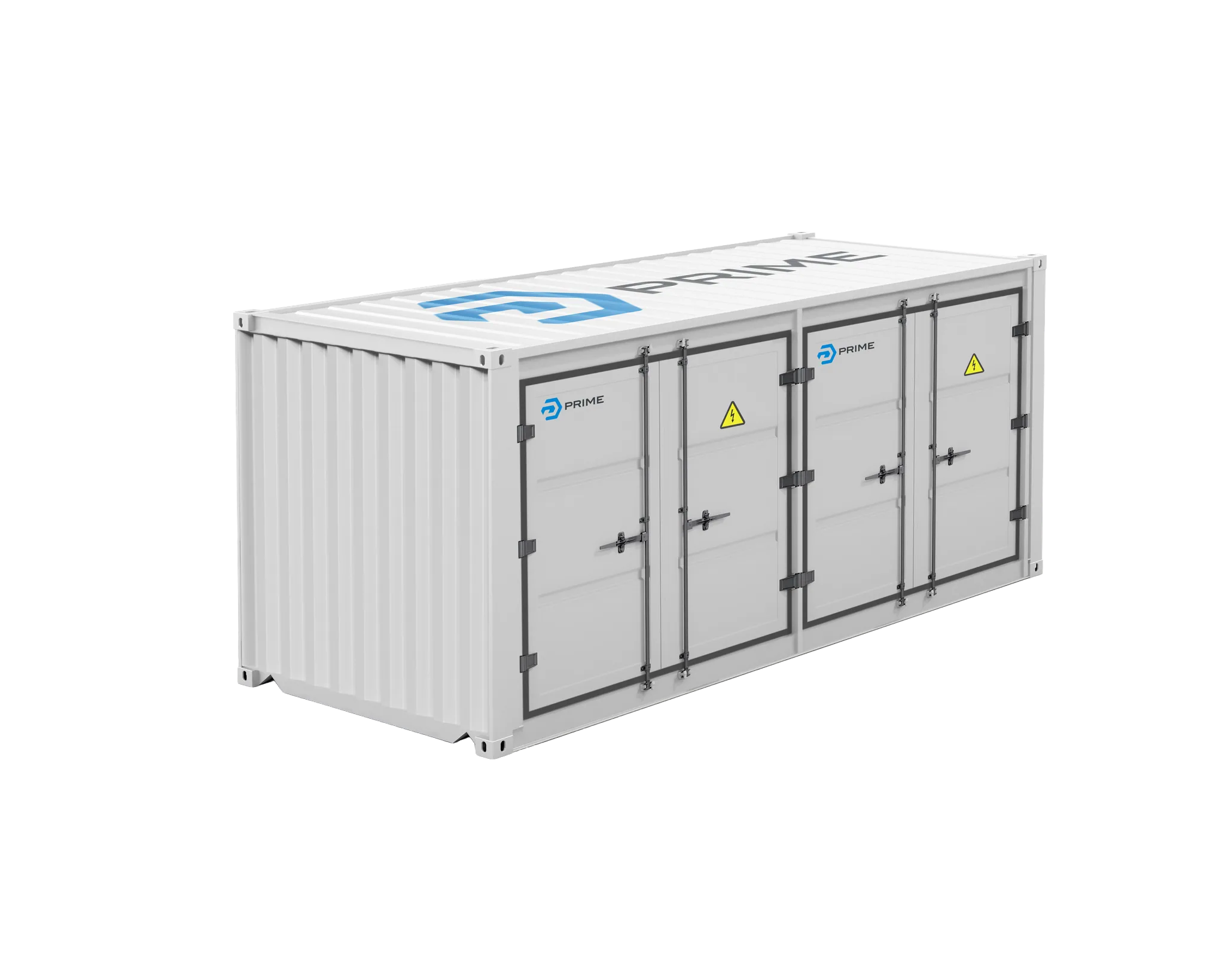
FIG.03 — POWER CONVERSION · 20FT SKID · MODULAR PCS
Round-trip efficiency
Flat efficiency curve across the real load range
Sustained from 20% to 100% load; not optimised only for peak conditions.
100–400 V DC bus. Modular from 20 kW per unit; scalable for behind-the-meter commercial and industrial applications. Suitable for low-voltage battery configurations and solar-plus-storage. Multiple units operate under a single EMS instance.
100–400 V DC
150–1000 V DC bus. 30 kW per module; modular and extensible for medium-scale industrial BESS and grid-tied applications. Covers battery configurations from low to medium voltage; suitable for containerized deployments up to several hundred kW.
150–1000 V DC
Up to 1500 V DC bus. Three-phase bidirectional converters from 1.7 MVA to 3.7 MVA per inverter; full skid configurations reach 7.86 MW. Liquid cooling for high power density and thermal stability. Grid forming capability as standard; suitable for weak grid and island mode operation.
Up to 1500 V DC
Integration
Deployment
04 / 04 Battery Management System
Protection and performance
across the full system lifetime.
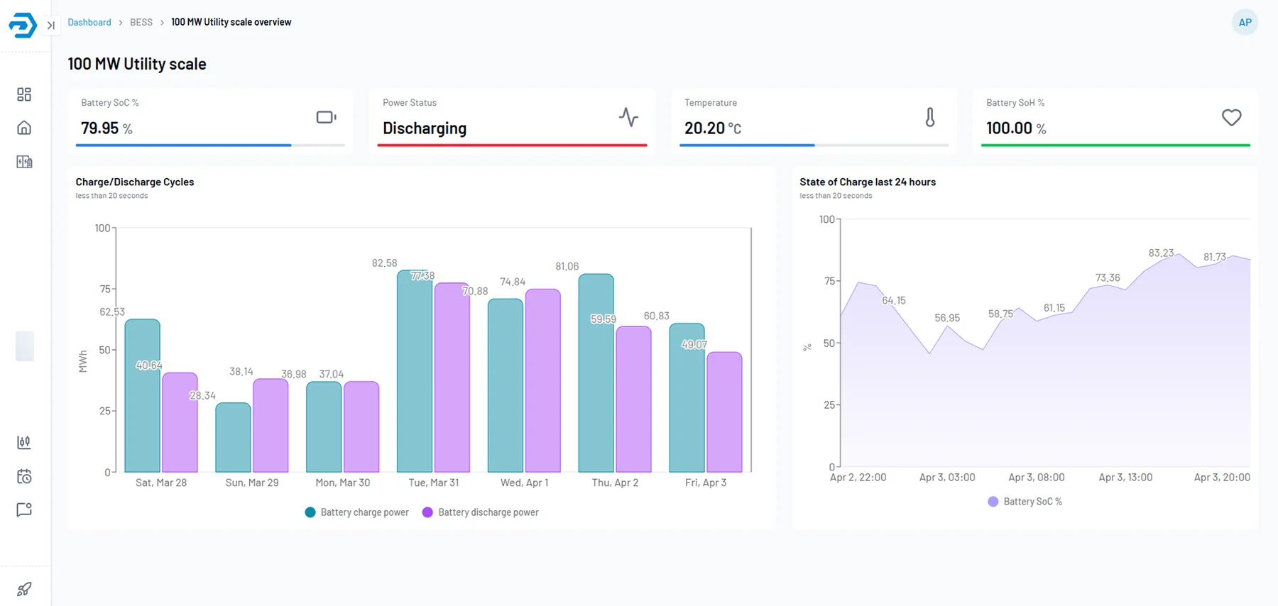
The battery management system in every Prime rack monitors each cell individually and enforces protection at both hardware and firmware levels; independently of the site controller or cloud. Faults are detected at the source, contained at the rack level, and reported up the stack before they affect system availability.
Protection and state estimation run on the same platform. State of charge, state of health, remaining energy, and maximum available power are reported continuously to the EMS; enabling accurate dispatch without operating the pack outside safe limits.
Cell-level monitoring
Every cell, monitored individually.
Each cell is monitored for voltage and temperature. Balancing engages the moment a cell drifts, contained at the rack level before it affects pack performance.
Depth of visibility
Four measurement layers, one platform.
- 01Cell
Per-cell voltage & temperature
Every cell is monitored individually across the full operating range.
- 02Module
Up to 8 temperature sensors
Hotspots are detected and isolated before thermal propagation.
- 03Rack
Fault containment
Faults are detected at the source and contained at the rack level.
- 04System
Reported to the EMS
State of charge, health, energy, and power are reported continuously to the EMS.
Emergency stop: A dedicated hardware input triggers immediate disconnection of all racks simultaneously, overriding any software state. The protection path does not depend on firmware execution or network communication.
Continuous isolation monitoring: The system monitors electrical isolation between the high-voltage bus and chassis ground at all times. A fault is detected and the system is isolated before it can create a risk to personnel or adjacent equipment.
Single-rack installation. Suitable for commercial behind-the-meter applications with smaller capacity requirements.
Small containerized systems. Parallel rack configurations scale current linearly with no hardware redesign.
Typical 20 FT container configuration. All racks operate under the same BMS and EMS instance.
40 FT and multi-container deployments for utility-scale storage. Single EMS manages the full installation.
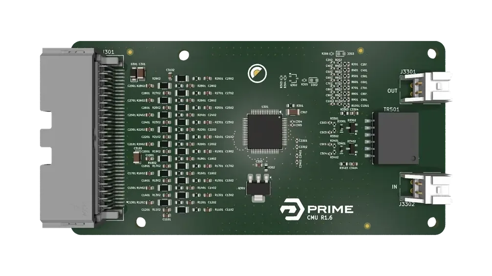
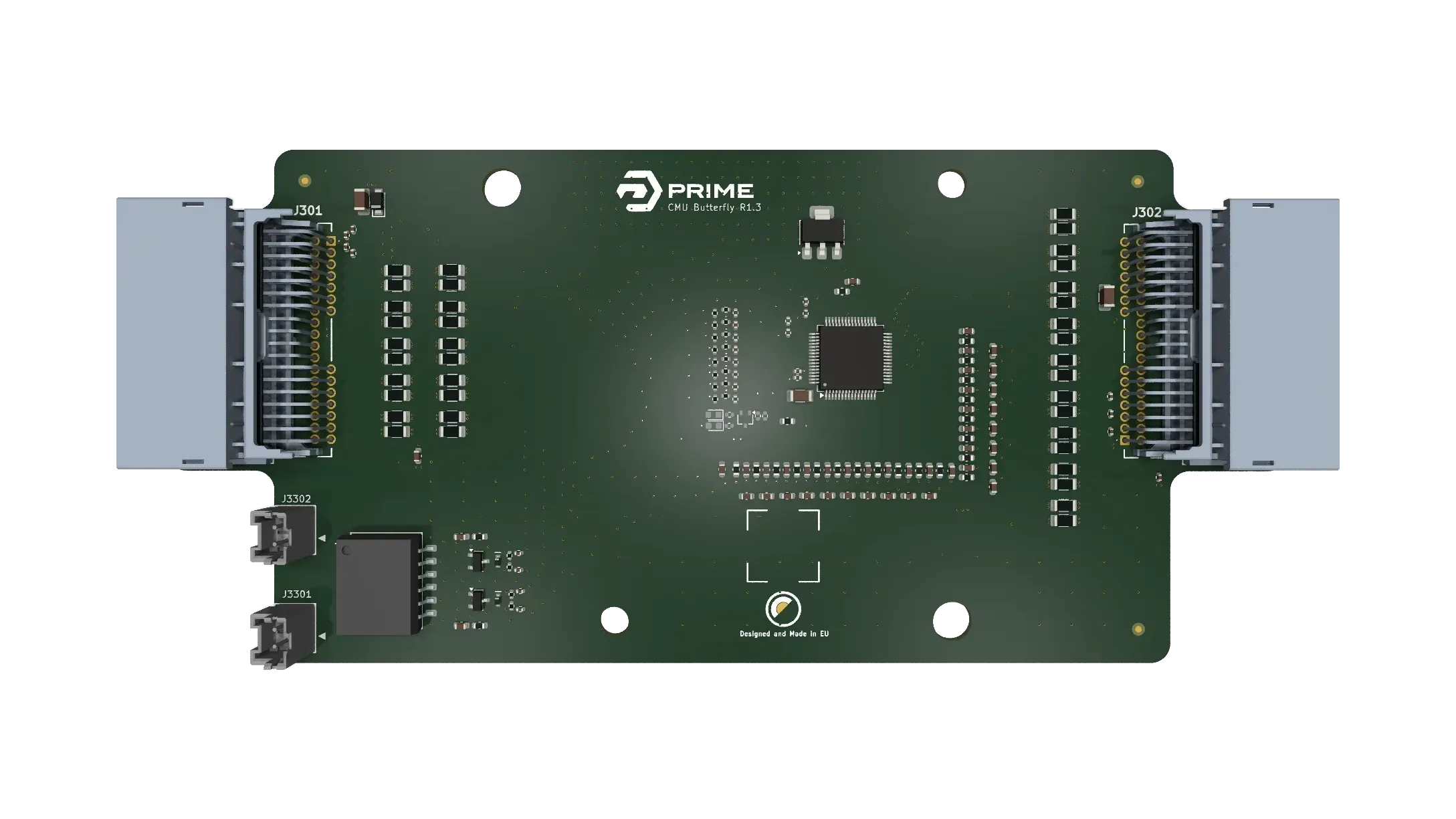
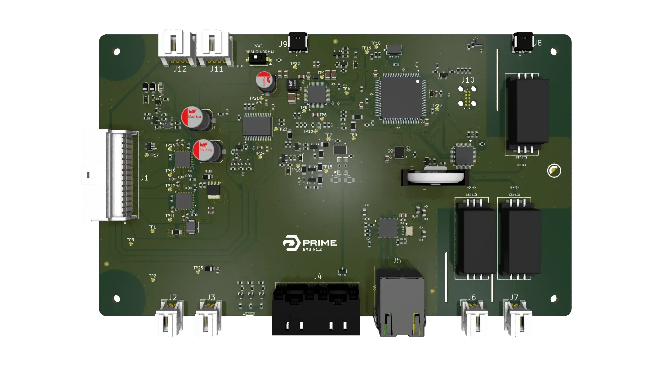
Engineered in-house
The control boards behind every pack.
What the BMS protects against
What the BMS reports to the EMS
See it run in a real operation.
Walk through the platform with our engineering team and size the right configuration for the project.